
Running Functional Tests
Test Setup
Next on the list was to perform a functional checkout. To accomplish this, I created a detailed test setup procedure and set up the unit as shown in Figure 1. The test equipment included the IMU, a power supply, a harness that connects the IMU to a serial-to-USB converter and the power supply, a serial-to-USB converter, and finally a test laptop.
Detailed Test Setup Procedure
IMU Preparation:
- Ensure the IMU is free of any physical damages, bent pins in the connectors, wire damage, and foreign object debris (FOD).
- Verify the IMU is clean and in good condition.
Power Supply Configuration:
- Set the power supply to the required voltage and current specifications for the IMU.
- Double-check connections to ensure polarity is correct to avoid any damage to the IMU.
Harness Assembly:
- Connect the harness to the IMU, ensuring all pins align correctly and the connection is secure.
- Connect the other end of the harness to the power supply and the serial-to-USB converter.
Serial-to-USB Converter Setup:
- Connect the serial-to-USB converter to the harness.
- Install any necessary drivers on the test laptop to ensure the converter is recognized and functioning correctly.
Test Laptop Configuration:
- Ensure the test laptop has all necessary software and drivers installed for data collection and analysis.
- Connect the serial-to-USB converter to the test laptop via a USB port.
- Open the data collection software and configure it to communicate with the IMU through the correct serial port.
Initial Power-Up:
- Power on the IMU and verify that it initializes correctly.
- Check for any error messages or abnormal behavior during startup.
Functional Checkout:
- Begin collecting data from the IMU.
- Perform a series of tests, including static and dynamic tests, to verify the IMU’s functionality and accuracy.
- Record the data and compare it against the IMU’s specifications to ensure it is operating within acceptable limits.
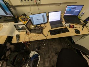
Figure 1: Test Setup Diagram
By following this detailed test setup procedure, I ensured that all components were correctly configured and that the IMU was ready for a thorough functional checkout. This systematic approach allowed me to efficiently verify the operational status of the IMU and confirm that it met the necessary performance specifications.
With everything in place, I began running the first set of functional tests. The initial goal was to confirm that the IMU powered up correctly and was capable of communicating with my system. Thankfully, the unit powered on without any issues, and communication was established seamlessly.
Testing Accuracy and Precision
The next phase involved testing the IMU’s accuracy and precision. I subjected it to various controlled movements and rotations, recording the output data. This data was then compared against the IMU’s specifications to ensure it was functioning within acceptable limits.
Verification and Validation
After several rounds of testing under different conditions, the results were conclusive: the IMU not only worked but performed exceptionally well. All values were within the specified range, confirming that the unit was fully operational and accurate.
Reflecting on the Gamble
Reflecting on the entire experience, I’m thrilled that my gamble paid off. Purchasing an expensive piece of equipment at such a low price was a risk, but the outcome was worth it. This IMU will be a valuable addition to my robotics projects, enabling more precise navigation and control.
Lessons Learned
This experience taught me several valuable lessons:
- Trust but Verify: Always perform thorough testing on second-hand or discounted equipment.
- Embrace Risks: Sometimes, taking calculated risks can lead to significant rewards.
- Stay Curious: Keep an eye out for opportunities, even in unexpected places like eBay.
Future Plans
Moving forward, I plan to integrate this IMU into my ongoing projects, leveraging its high accuracy and reliability. Stay tuned for more updates as I continue to explore and push the boundaries of robotics and engineering.